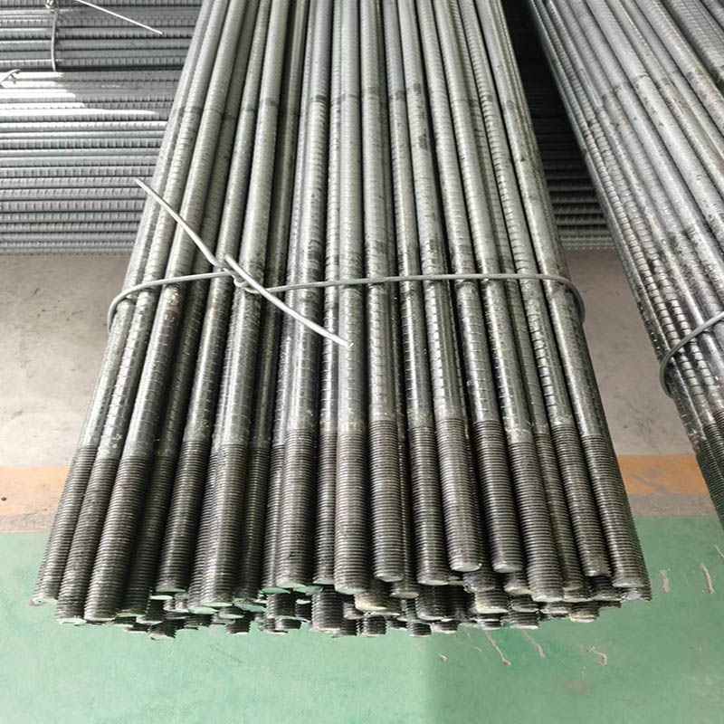
Construction Plan and Monitoring for Anchor Bolt Support
Xintai Ruiyu Mining Materials Processing Co., Ltd. analyzes the construction plan and monitoring for anchor rod support for new and existing clients:
I. Construction Process
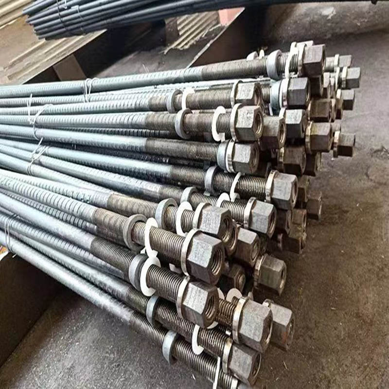
(1) Structural Requirements for Anchor Rods
1) Anchor rods shall be HRB335 grade Φ22 steel bars, with lengths ranging from 8.2 to 10 meters.
2) Vertical spacing between anchor rod rows: 1m; horizontal spacing: 1m.
3) Anchor rod inclination angle: 12.5°.
4) Cement mortar with strength grade no lower than M10 shall be used for anchor rod grouting.
5) Shotcrete thickness: 10cm.
6) Reinforcing mesh: φ10 steel bars spaced at 100mm intervals.
7) Grouting pressure is 0.6 MPa, with adjustments possible based on specific conditions.
(2) Process Flow
1) Anchor rod construction process:
Earth excavation → Slope facing finishing → Surveying and layout → Drilling rig positioning → Drill rod connection → Hole alignment → Angle adjustment → Drilling (Connect drill rods) → Drill to design depth → Insert anchor rod → Pressure grout and cure → Remove rust from exposed main reinforcement → Install crossbeam
2) Shotcrete surface layer construction process: Prepare vertical surface → Weld steel mesh → Dry mix concrete material → Sequentially activate power, air, and water switches → Perform shotcrete operation → Cure concrete surface layer.
(3) Operational Procedures
1) Slope Excavation
Anchor rod support shall be implemented in layers and sections per design specifications, ensuring simultaneous excavation, support installation, and concrete spraying. Excavation of the next layer shall not commence until the sprayed concrete of the upper working surface is completed. During mechanical excavation, over-excavation of slope walls, loosening of slope soil, or damage to retaining structures is strictly prohibited. To prevent slope soil collapse, the following measures may be applied to unstable soil:
a) Immediately spray a thin layer of mortar or concrete onto the trimmed sidewall; drill holes after setting.
b) Install steel mesh on the working surface, spray the concrete facing, then drill holes and install soil nails.
c) Excavate in small horizontal sections.
d) Form the excavated sidewall into a slope; clear the slope after drilling holes and installing soil nails.
e) During excavation, vertically drive steel bars and steel pipes into the excavation face or inject grout to reinforce the soil.
(4) Drilling and Anchor Bolt Fabrication
1) Ensure precise drilling positions (vertical, horizontal, and angular) to prevent uneven heights and intersecting holes.
2) Drill 100–200 mm deeper than the design depth to prevent insufficient hole depth.
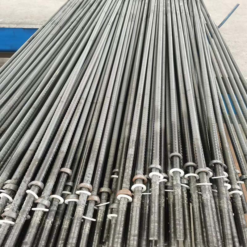
3) Anchor rods shall be fabricated by designated personnel. Extensions shall use straight threaded joints. To ensure anchor rods are centered in the borehole, install one locator every 1500 mm along the rod. Insert anchor rods immediately after drilling to prevent hole collapse.
(5) Grouting
1) Inspect grouting pipes for cracks or blockages before use. Ensure joints are secure to prevent rupture and grout leakage under increased pressure. Insert grouting pipes simultaneously with anchor rods. Seal the borehole opening only after grout is observed emerging from the hole during injection.
2) Flush grouting pipes with water prior to injection to wet the pipeline. Clean grouting pipes and equipment promptly after injection. Allow natural curing for no less than 7 days post-injection.
(6) Shotcrete
1) Before shotcrete application, the reinforcing mesh within the surface layer must be securely fixed to the slope wall and meet the specified protective layer thickness requirements. The mesh may be anchored using reinforcing bars inserted into the soil and must remain stationary during concrete spraying.
2) Welded wire mesh shall have a permissible deviation of 10 mm per mesh. When laying the mesh, the overlap length on each side shall not be less than one mesh side length.
3) The mix design for shotcrete shall be determined through testing according to design requirements. The maximum aggregate size should not exceed 12 mm. Operators shall receive prior training to ensure the water-cement ratio and quality of shotcrete meet specifications. Prior to spraying, conduct comprehensive inspections and trial runs of machinery, air supply, water supply, and electrical circuits. Spray from bottom to top, maintaining a nozzle-to-surface distance of 0.8–1.5m. Direct the jet vertically toward the surface. When spraying over reinforcement, fill one side first before spraying the opposite side laterally to prevent voids behind the bars. To ensure the sprayed concrete thickness meets specifications, short steel bars may be vertically inserted into the side walls as markers.
4) To enhance support effectiveness, add 3%–5% early-strength agent during concrete spraying. Subsequent operations may proceed only after the concrete has initial set for 2 hours, followed by continuous water curing for 5–7 days.
(7) Finished Product Protection
1) Apply anti-corrosion treatment promptly to the non-anchored sections and anchor heads of bolts.
2) Immediately install bolts after drilling holes and grout them promptly to prevent hole collapse.
3) Plan bolt installation sequences rationally. Ensure adequate lighting for night operations to prevent inaccurate mortar mix ratios.
4) During construction, take care to protect positioning control points.